This blog was started to serve as a record my university work back in 2009, in the 16 years (oh god) since I’ve changed and improved a lot and what’s shown here isn’t representative of my current work. I’m leaving it as an archive in the unlikely event any of it proves useful or interesting to someone.
I hope to occasionally post updates for various projects time permitting.
Why can’t a thing be made out of the thing that it controls?
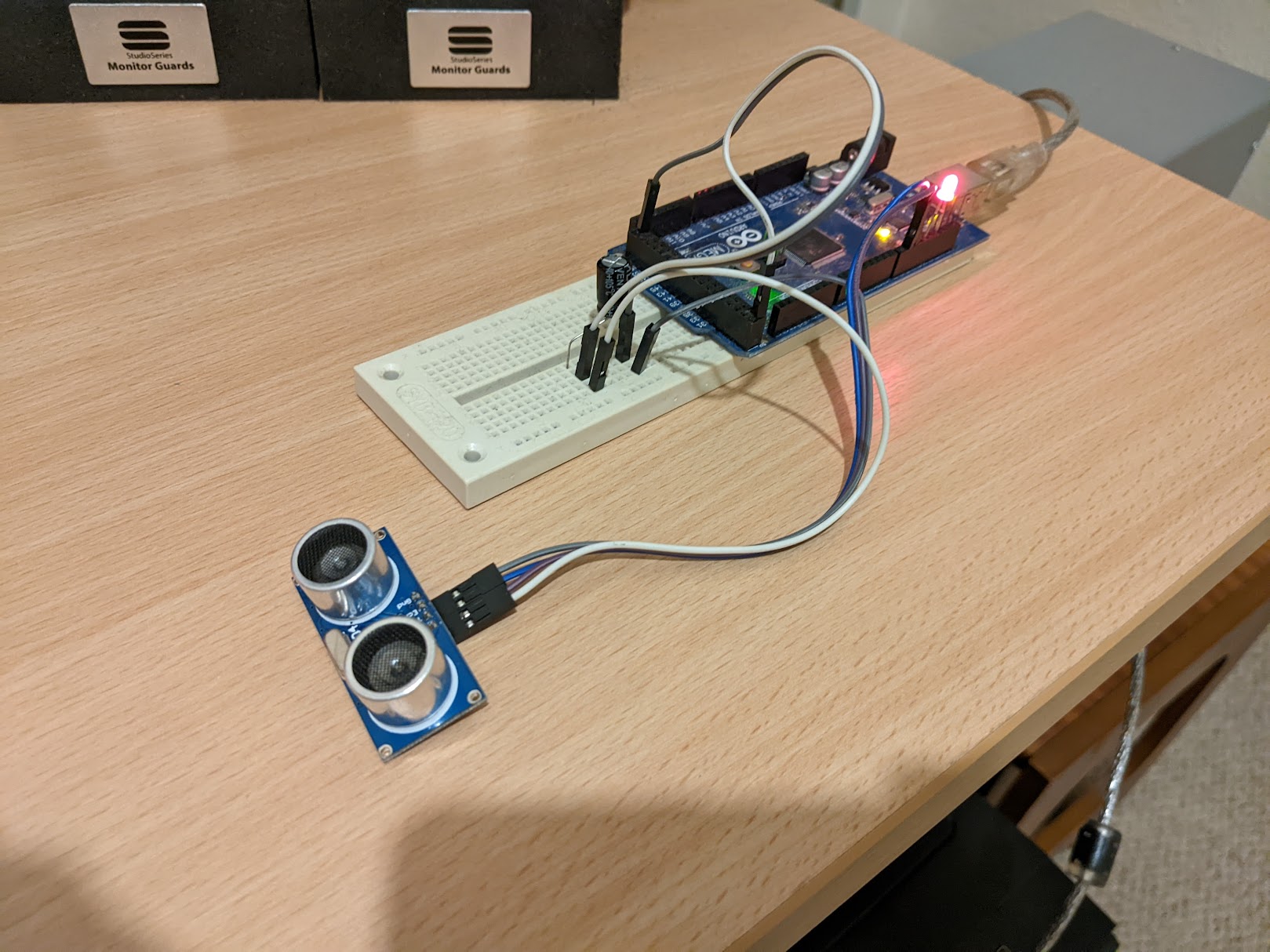
After messing with using Arduino as a HID keyboard for a simple push to talk foot pedal I had the idea to create a USB plug in and play volume control with a novel interface. Using an ultrasonic range-finder I could control the volume by raising and lowering my hand over the ultrasonic beam. The idea of controlling sound with sound tickled me so I set about building a prototype.
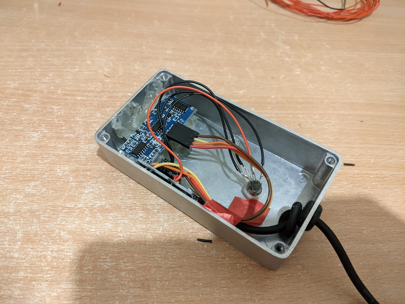
I found that the range finders had reliability issues until I put a capacitor across the VCC and ground pins for decoupling and filtering. I had a 470uF capacitor to hand but this was likely overkill for the application but probably doesn’t hurt too much. I also added an RGB indicator LED that would change colour based on the volume set, the higher the volume the warmer the colour of the LED.
With the Arduino HID project library it was simple to send HID keyboard media key presses from the Arduino. I would be using MEDIA_VOLUME_UP and MEDIA_VOLUME_DOWN which each increment audio relatively. Ideally I’d use HID_CONSUMER_VOLUME instead for an absolute scale.
I programmed the control to work between 10 and 40 centimetres above the range-finder which corresponds to 0 to 100% volume. Putting your hand into the beam below 10cm mutes the volume. As there’s no way for the device to know what the volume of the computer currently is it sends 100 MEDIA_VOLUME_DOWN requests so it can be reasonably sure the starting volume should be zero. Pulling your hand horizontally out of the beam, headroom depending, gives a value greater than 80cm which it interprets as no reading, the existing value from when your hand was in the beam is held.
I added a rolling array of distance readings and averaged them for a bit of hysteresis so that changes would be smoother and errant readings ignored. It was important that the volume not suddenly jump up immediately.
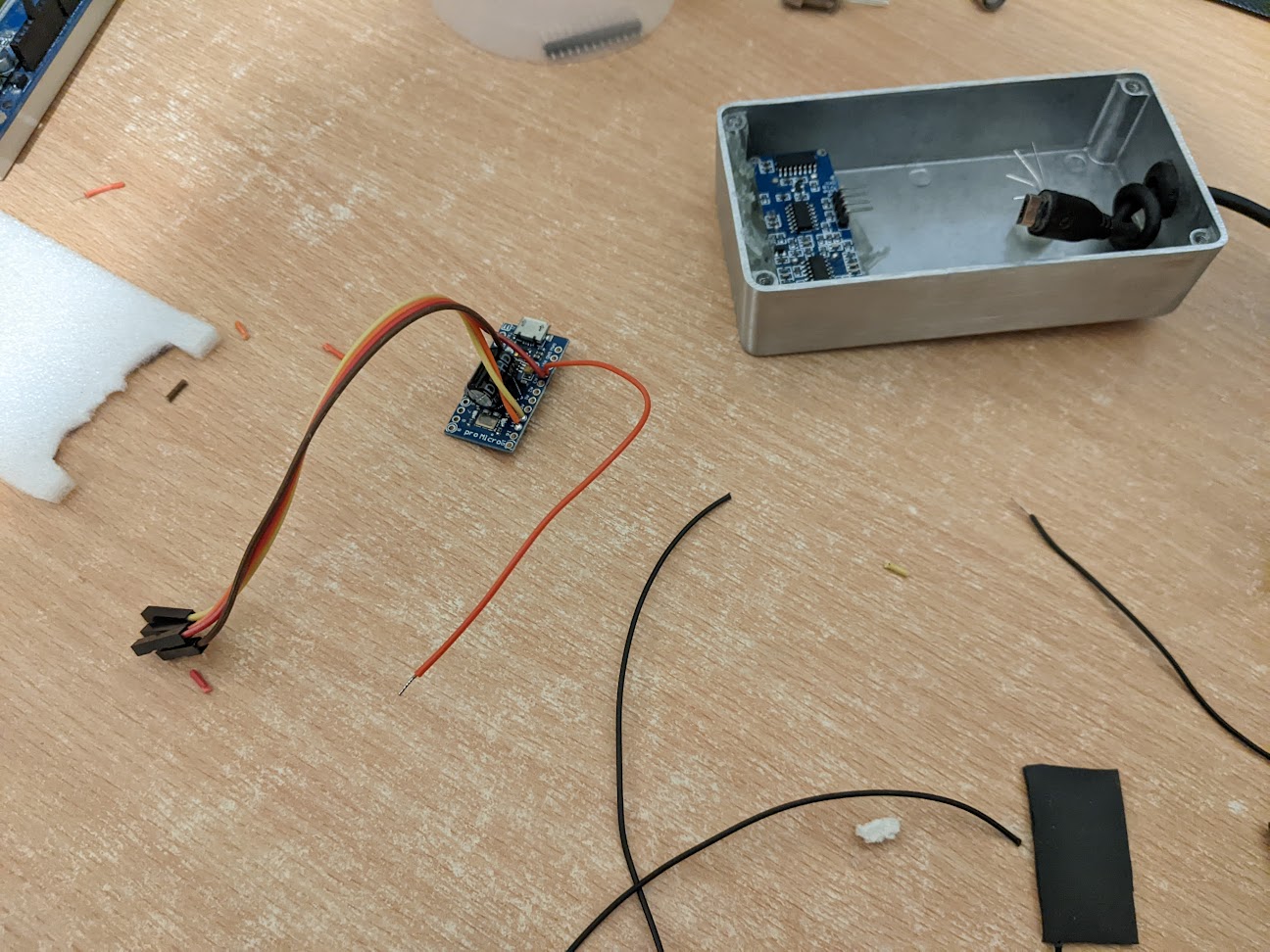
For the real thing I wanted to make it fairly compact so opted to go with an Arduino Pro Micro, which has an integrated USB controller in its ATmega32U4 allowing me to use it as a plug-in-and-play USB HID (Human Interface Device) without any special drivers.
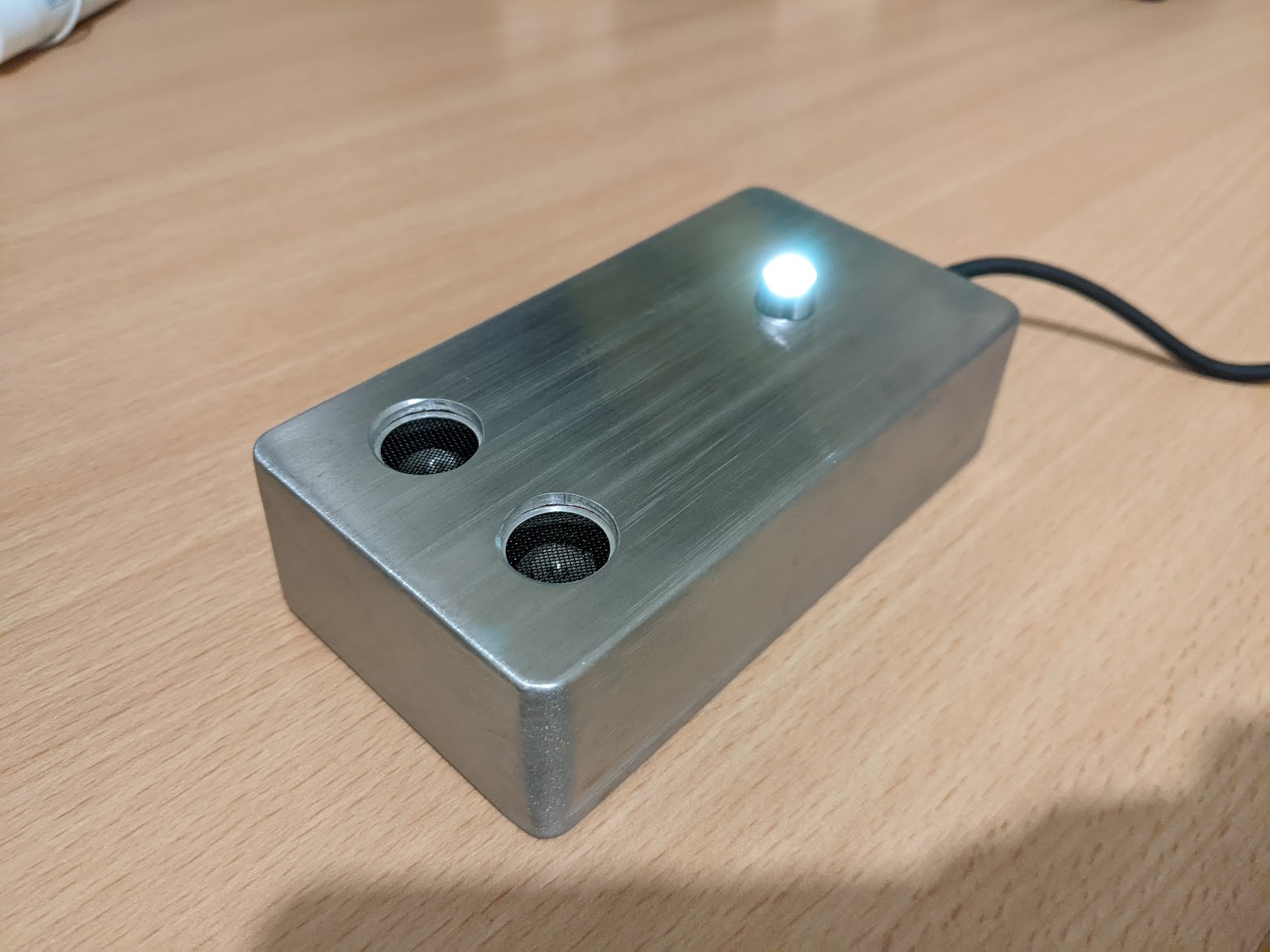
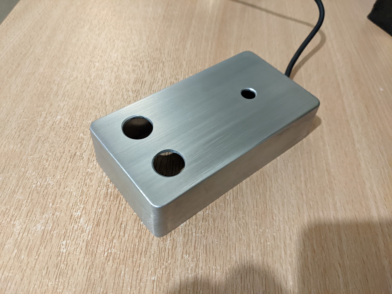
For the enclosure itself I opted to use a diecast aluminium project box and do the brushed aluminium finish that I had used before on the SIP doorbell project. I checked that everything could fit nicely, I could maybe have gone for a slightly smaller enclosure but was happy with the size.
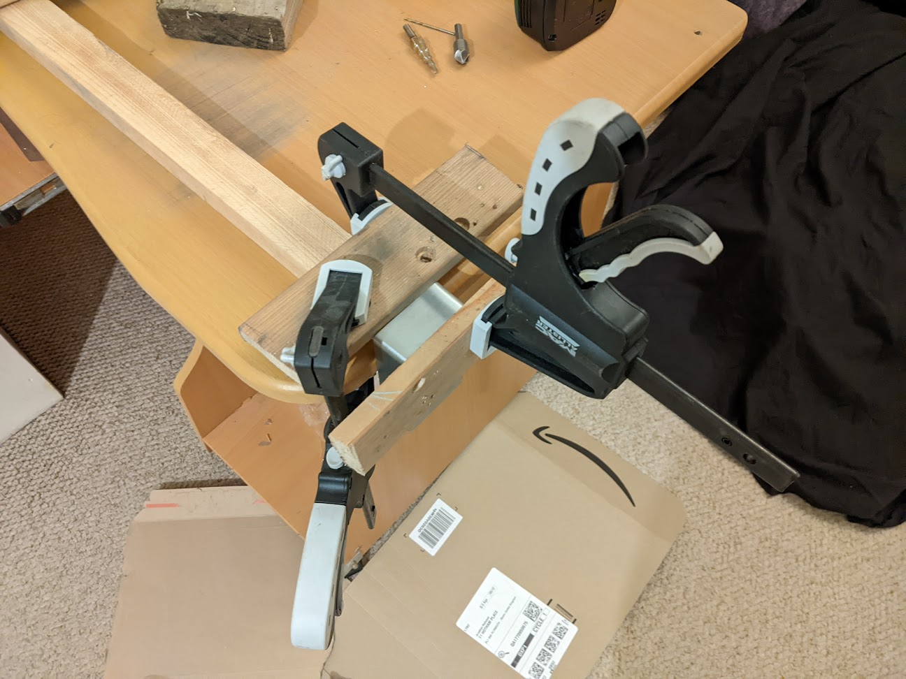
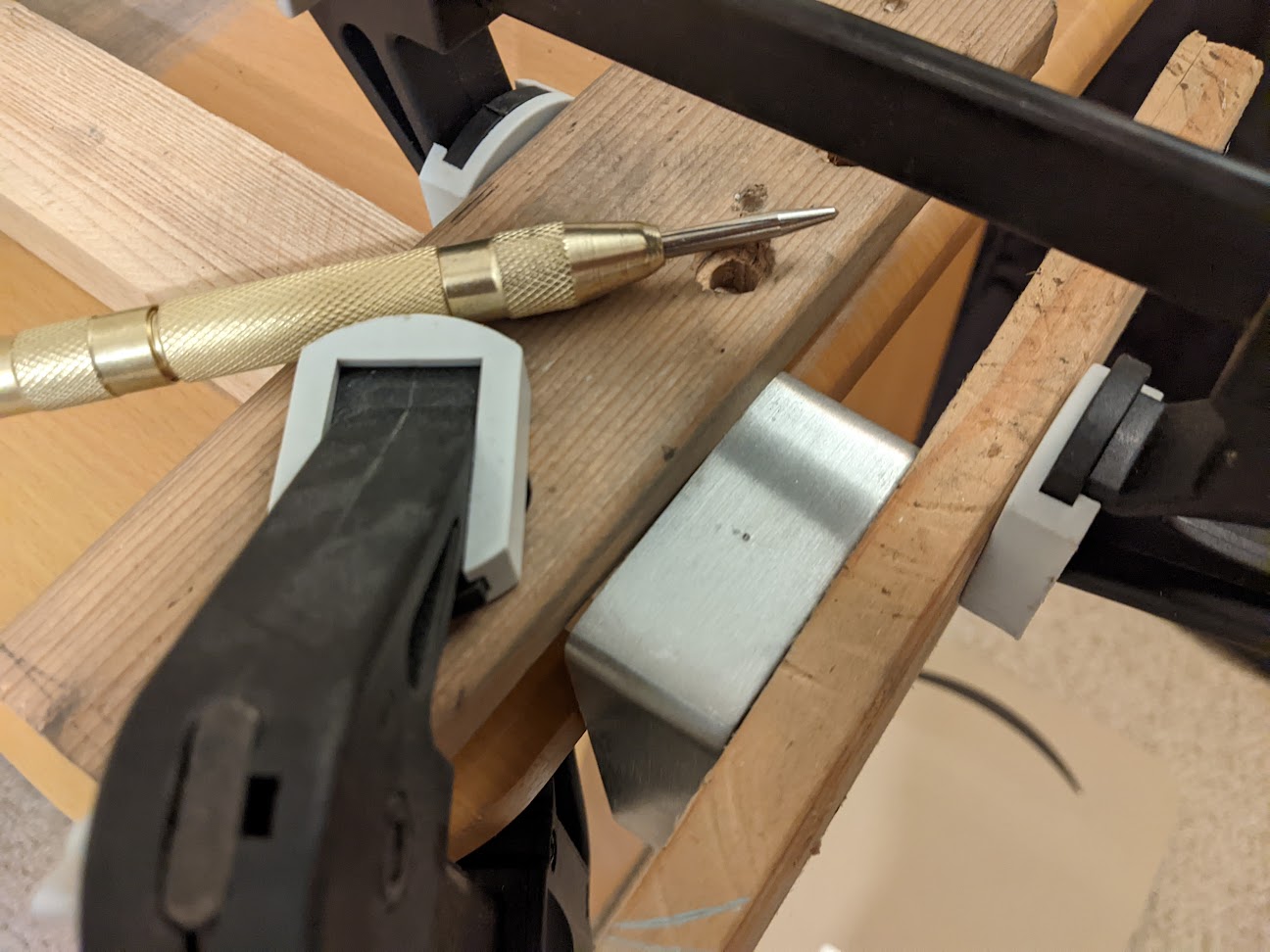
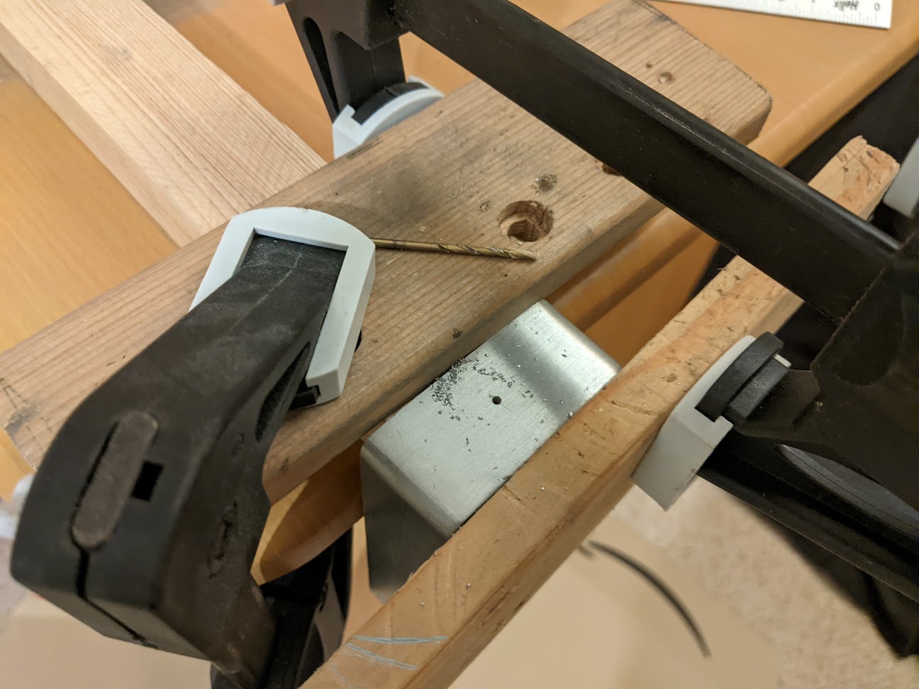
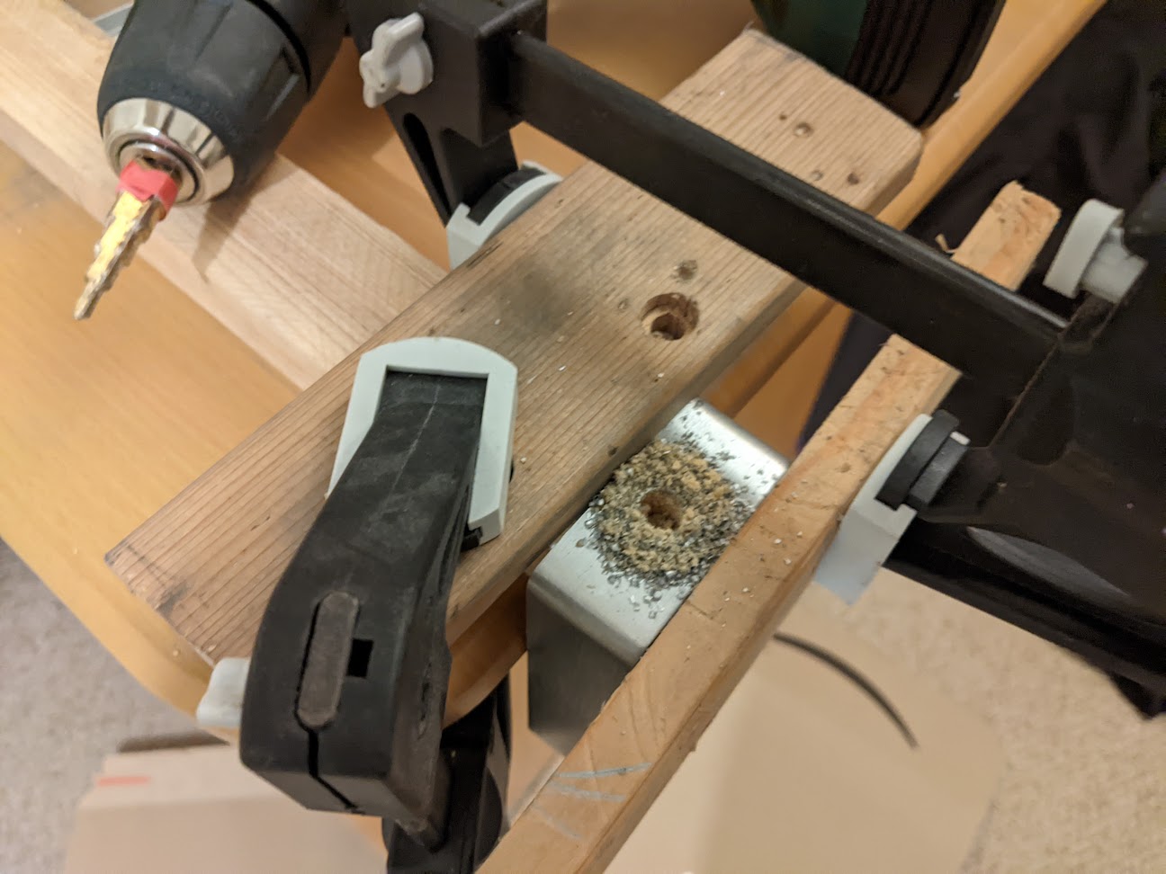
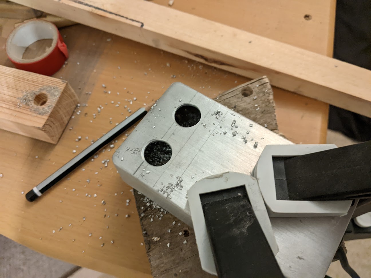
Using a pencil I scribed out the layout, worked out an elaborate way to securely clamp the enclosure as well as back the hole with wood to hopefully reduce the chance of chipping on the back side. Using a centre punch then a pilot hole before the step bit kept the holes properly positioned, I also marked the step bit with tape to show the desired diameter. After drilling I used a countersink to deburr the holes.
With the holes drilled I was then able to offer up the rangefinder to make sure it would work in-situ and not be affected by the aluminium around it. With that confirmed working I moved on to the brushed finish.
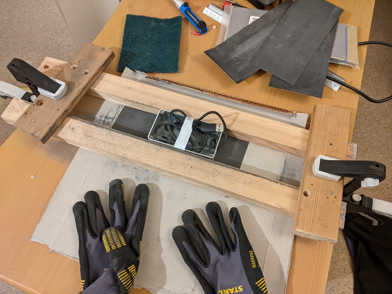
I ran the enclosure up and down as a sled between two pieces of wood clamped into position over increasingly fine abrasive paper until eventually reaching the desired finish.
Next came final assembly, I soldered the capacitor directly to the Arduino along with header wire for the pins on the range-finder and the wires for the RGB LED which I potted into a mount for tidy installation. I threaded the micro USB cable through a rubber grommet and put a knot in it as a strain relief. I also made use of a lot of hot glue to hold the range-finder and Arduino in place.
Something I was hoping would be cured after rebuilding was the bug where the Arduino would appear to crash and lose all its target values causing the system to drain. Unfortunately the problem is still there but since everything is more robust and better thought out I will hopefully be able to figure out the cause.
So far I have found that it doesn’t happen when power isn’t being supplied to the pumps and valves and it looks like the pumps are the main culprit which is odd as it should be isolated on the relay array. A separate power supply for the pressure sensors also doesn’t help. Right now the only thing I can think of is that the pressure sensors are right next to the pump motors so they could be picking up EMF and tripping the Arduino.
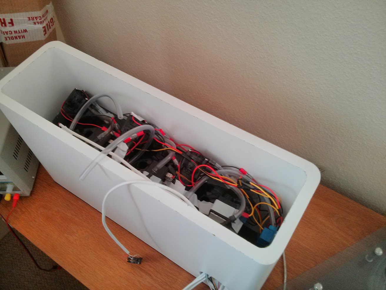
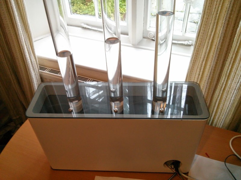
After wiring and plumbing everything the next stage was to put it back in its housing, attaching the pressure sensors and wiring everything together. This time more of the power circuitry is inside the unit so only the 12V supply, single 5V supply, 6 control wires for the pumps and valves and the 3 pressure sensor data wires are external. After testing all the connections and relays I could then start the attaching the lid and tubes.
After putting a little water in each of the tubes I was happy to find that everything appeared to be working. The self priming pumps took a little while to start moving water but when they did, they moved it nice and quickly. The pressure sensors needed a bit of calibrating because they were not positioned the same way as before.
Not finding any leaks I made the pumps fill the tubes as far as they could with the water already in the system and then filled it the rest of the way, the theory being that there physically isn’t enough water in each tube’s reservoir to overfill the tube, even if everything goes horribly wrong with the control system.
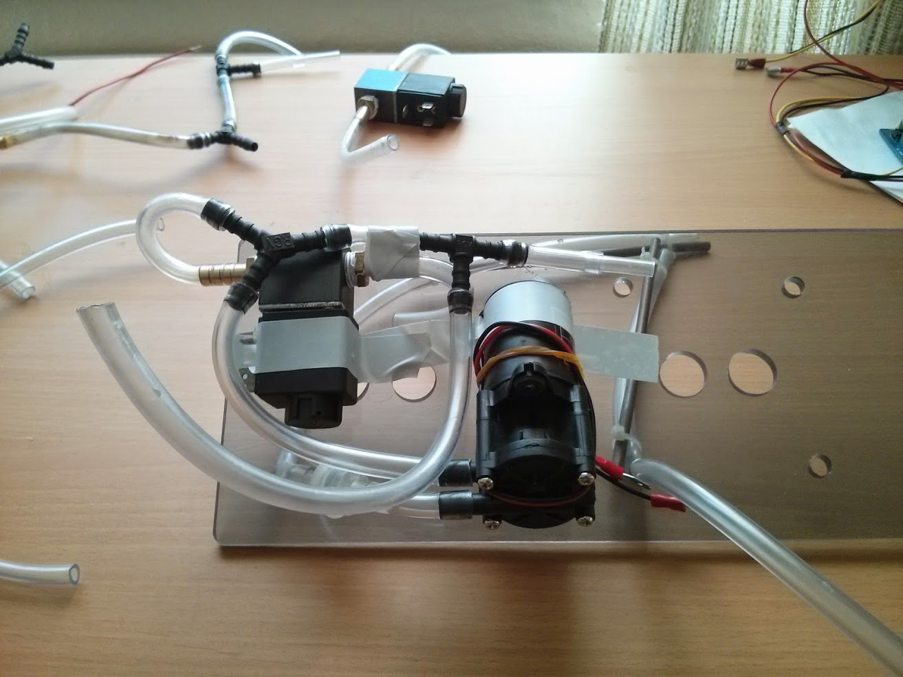
One of the biggest challenges of the original project was the routing of pipes so that they didn’t kink and cut off flow. With the extra space, shorter tubes and better planning I was able to work out a way to fit it all together.
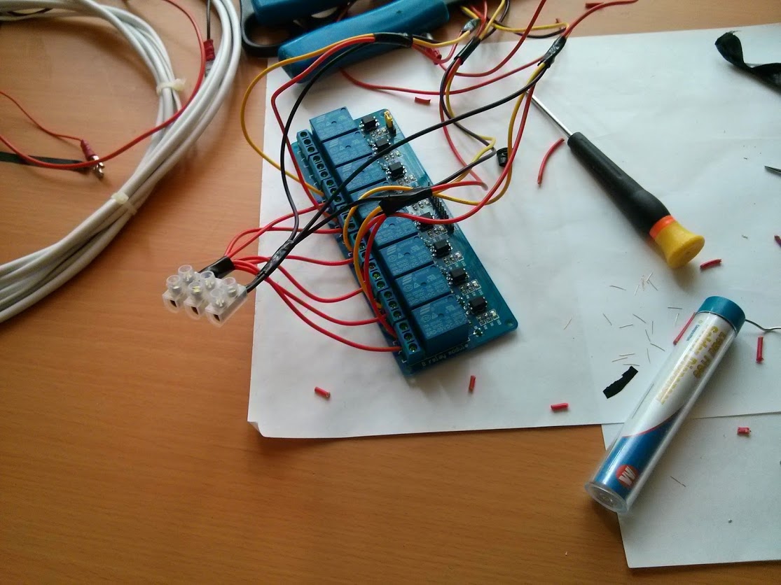
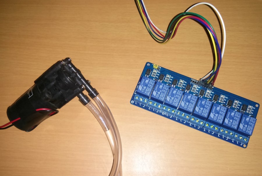
It’s taken a while but I’ve finally gotten around to doing the wiring for the relay array. This involved striping and tinning wires to stop them fraying in the screw terminals. The wires I am using are much higher gauge than they really need to be for the 12V 2A maximum going through them.
The original pumps I used had spade connectors but unfortunately the self priming ones I have don’t so I’ll be getting some when I get the chance, I want to make it easy to swap out parts and avoid having anything soldered when it doesn’t need to be. I’ve also connected a pair long wires to the main power terminal to take it to the external power supply.
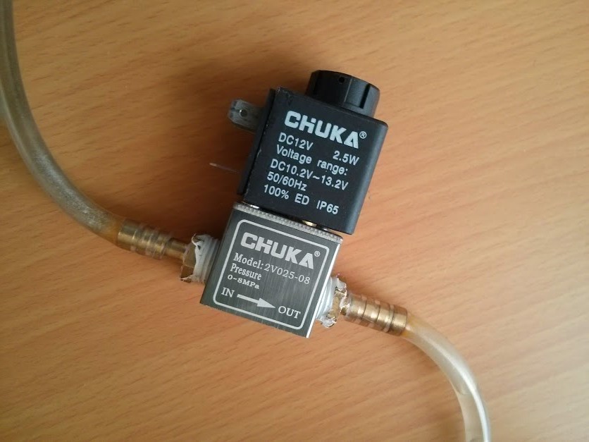
The valves appear to do what I want and have been attached to the pumps, I’ve placed them before the intake so that water remains in the pump and means it doesn’t have to self prime but can when it’s first turned on.
I checked my solenoid valves and found that they still had water in them after a year and that the hose fittings had corroded slightly and stained the tubes. I drained them and thankfully they still worked. I’ll have to make sure I remove all the water from it when it is not in use.
After getting and fitting the spade connectors my next concern is with the plumbing and how to make the most of the space provided by getting rid of the hand primer pumps and how to wire the three pressure sensors. I’ll probably also have a look if there is now a better way to send control signals to the Arduino from the net.
Something that was unexpectedly difficult for me was calculating the state of the tide as a percentage so I decided to post what I came up with in-case someone needs it.
It takes one of the day’s high tide times and the time you wish to know the percentage of, both in hours.
public function get_level($high, $time){
    return cos(pi()/6.2103 * ($time - $high)) * 50 + 50;
}
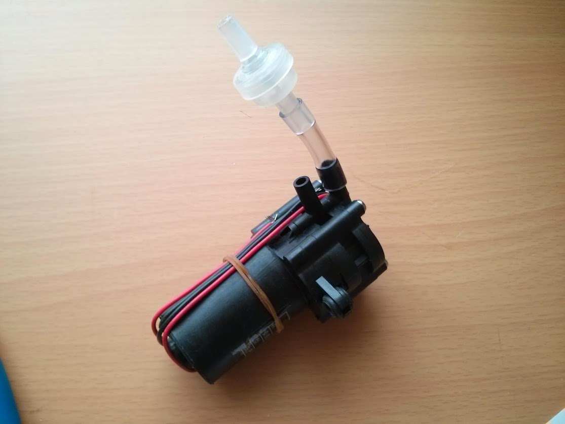
The 3 new self priming pumps were the first to arrive, the ones I ordered cost £7.12 each, have a max current of 1.2A at 12V which is less than the old pumps, hopefully without a significant loss of ability to move water. One thing that I wasn’t sure about was if the the pumps already incorporate a one way valve to prevent water flowing backwards though them but after testing I found that it would be necessary so I’ve ordered some.
The second thing was the new relay array for controlling the 12V supply for the solenoid valves and pumps which tidies things up and reduces the amount of soldering. The pressure sensors will be part of a separate circuit board.
Along with the valves I’ve also ordered some more 6mm PVC tubing. With the time for orders to arrive and without any hard deadlines and the inevitable flexibility of self imposed deadlines progress is slow but I’m hopeful it’ll be functional fairly soon.
The first complete Canute which was presented as my final year project made use of ultrasonic range-finders to detect the water levels in each reservoir and therefore infer that whatever water wasn’t in the reservoir must be in the tube. This worked to a point but since it was only measuring over a 10cm range in the reservoir and the range-finder was only accurate to 0.5cm there were only 20 points along the display tube which it would come to rest. Additionally the ultrasonic range-finders were sensitive to water droplets on the mesh in front of the detector and contact with them and the internal shelf they were on made them temperamental. Another problem was that each of the electric pumps it used required manual priming with hand pumps. This was all manageable but it did require baby sitting.
For the degree show my project would have to be left alone for extended periods so I decided to use the week between the hand-in and the degree show to upgrade it to make use of water pressure sensors instead of the ultrasonic range-finders. I was pleased with their performance, however since I only had the two I had to wait till the day of the show opening to get the third and fully test the system.
Unfortunately something went wrong on the main relay board controlling the centre tube and something was causing the Arduino to restart, I had a spare Arduino which still crashed, the code had not changed significantly and nobody could identify the cause of the problem. It was a bit disappointing especially since it had been working. Canute was living up to its name, but it was still good to have it at the show, despite the problems.
I hate leaving things unfinished.
Now there is nothing at stake I’ve began the process of redesigning the electronics and ordering new parts to get Canute working again. The plan this time involves self priming pumps which means I’ll no longer have to worry about pumps running dry or have to lift the tubes in order to prime them. Not having the hand primer pumps taking up room will also be helpful.
Instead of using the circuit boards I soldered myself I will use a prebuilt relay board and also include the Arduino inside the unit. Instead of the lab power supply I used before I’ll use a more compact laptop charger type one which might also be able to fit inside. Ideally I will also include an Ethernet shield so all you have to do is connect the unit to an internet connection and power and it could fetch tidal data that way.